How to read Japanese mechanical drawings (JIS)
Not everyone can understand deeply and read Japanese mechanical drawings properly. So how to read the drawing properly? Let’s learn with me how to read Japanese mechanical drawings in the article below.
What is the JIS standard?
JIS Standard (English: Japanese Industrial Standards) is a Japanese industrial standard used in industrial activities in this country.
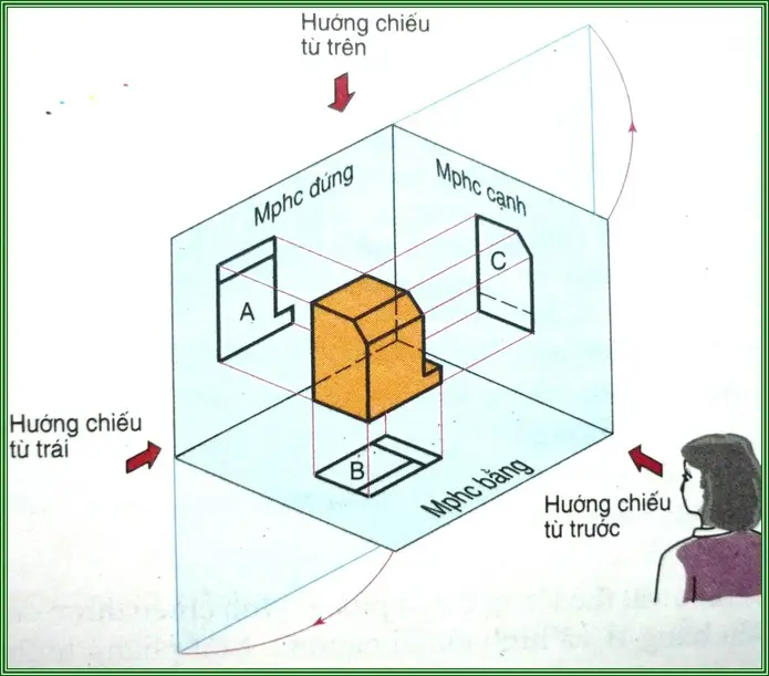
Unlike drawings in Vietnam, Japanese drawings have an edge-to-vertical projection layout and are used according to JIS standards – the 3rd angle projection method (illustration). In addition, when the processing details are complicated to clearly show the requirements to be processed, people will use cutting drawings and extract drawings.
Instructions on how to read Japanese mechanical drawings (JIS)
To understand how to layout and build projections according to JIS standards, please follow the reading below.
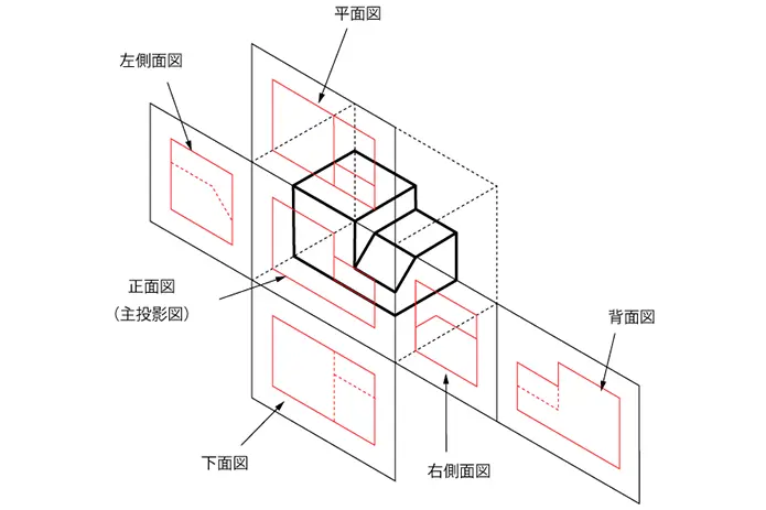
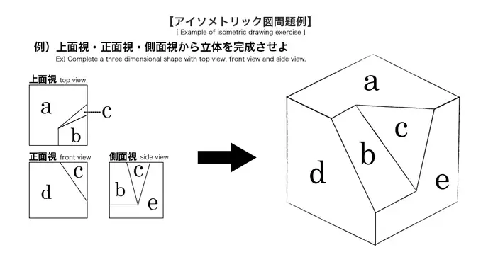
Suppose when there is a rectangular box with the symbol planes in the figure:
- Looking from the outside, you will see the object passing through the planes and showing the faces of the rectangular box with the corresponding lines (visible or hidden).
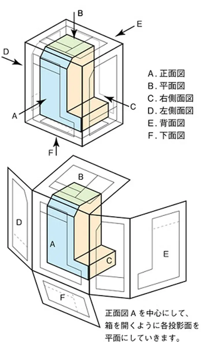
- If you open the planes of the box (shown below) you will get the corresponding projections of the object on the respective faces.
- The planes of the box that are spread on the same plane will be the projection planes of the object.
As a result, each object will have 6 corresponding planes, but usually only 3 faces are enough. If it’s simple, it’s 2 projections, while it’s complicated, it takes up to 6 faces to be projected and the cut and extracted images to show all the objects. In which, the projection always has the main view to be able to see the whole object.
Draw projection from bright object 2D model
In addition to applying the above standard, you also have to know how to imagine the object to be able to draw accurately and quickly.
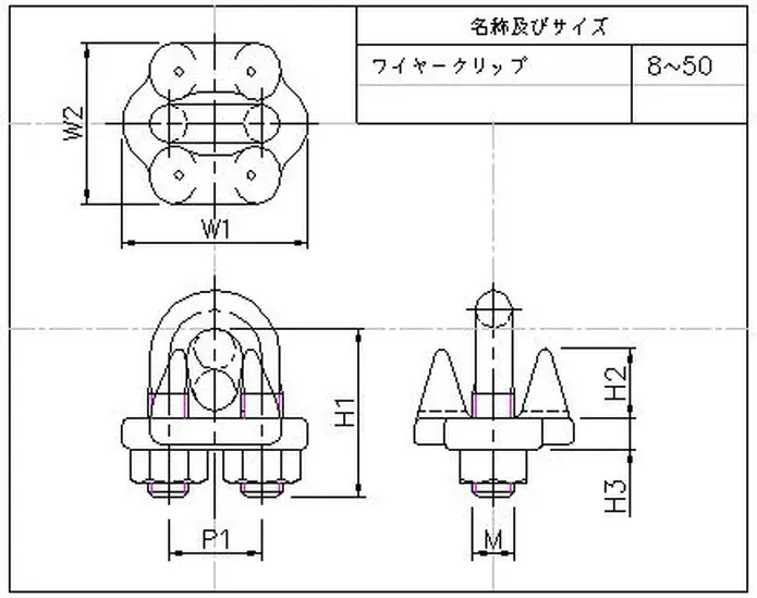
– From the object, you will draw the following 2D projections:

– You will draw and arrange the corresponding projections as above.
When drawing, you must draw the faces that show the most clearly and easily visualize the object. At the same time, limit the dashed directions and the number of projections just enough to visualize the object.
From the projection of 2D models to build real objects
In order to build a real body from a 2D view, technicians need to master the rules of viewing the image above.
From 2D drawings to build objects, you must visualize 3D objects. This is the ultimate goal of reading engineering drawings.
– From the 2D projection, build the object as follows:
When starting to edit, you should sketch the object from the projection so that the image uses the object. Then, based on the remaining shapes to build the next object, you can cut or add blocks.
Reference source: blog.mecsu.vn
-
Jigs design 05
Price: ContactMachining jigs contribute to a higher degree of mechanization and automation of precision mechanical manufacturing. On machine tools to cut and cut, it is necessary to carry out the process of assembling details. Therefore, the jig is an indispensable technological equipment in the processing process on metal cutting machines. A fixture that meets the standards for good positioning and clamping is required.
Design and manufacture jigsaws – JIG at IDEA is the best choice for you
Prestige and top quality with experience working with more than 150 customers from markets with strict requirements for top standards such as Japan and the US.
Working motto “IDEA brings the best to customers”, the product that you receive is always the best quality.
Customer service always ensures fast – accurate – dedicated 24/7 at all stages to create trust and absolute satisfaction from customers.
Reasonable cost competitive with the marketContact details:
Address: 2nd Floor Lot 100 High-rise Factory Linh Trung Export Processing Zone I, Linh Trung Ward, Thu Duc City
Tel: (028) 73 00 4577 line 631
Email: sales@ideatechmart.com -
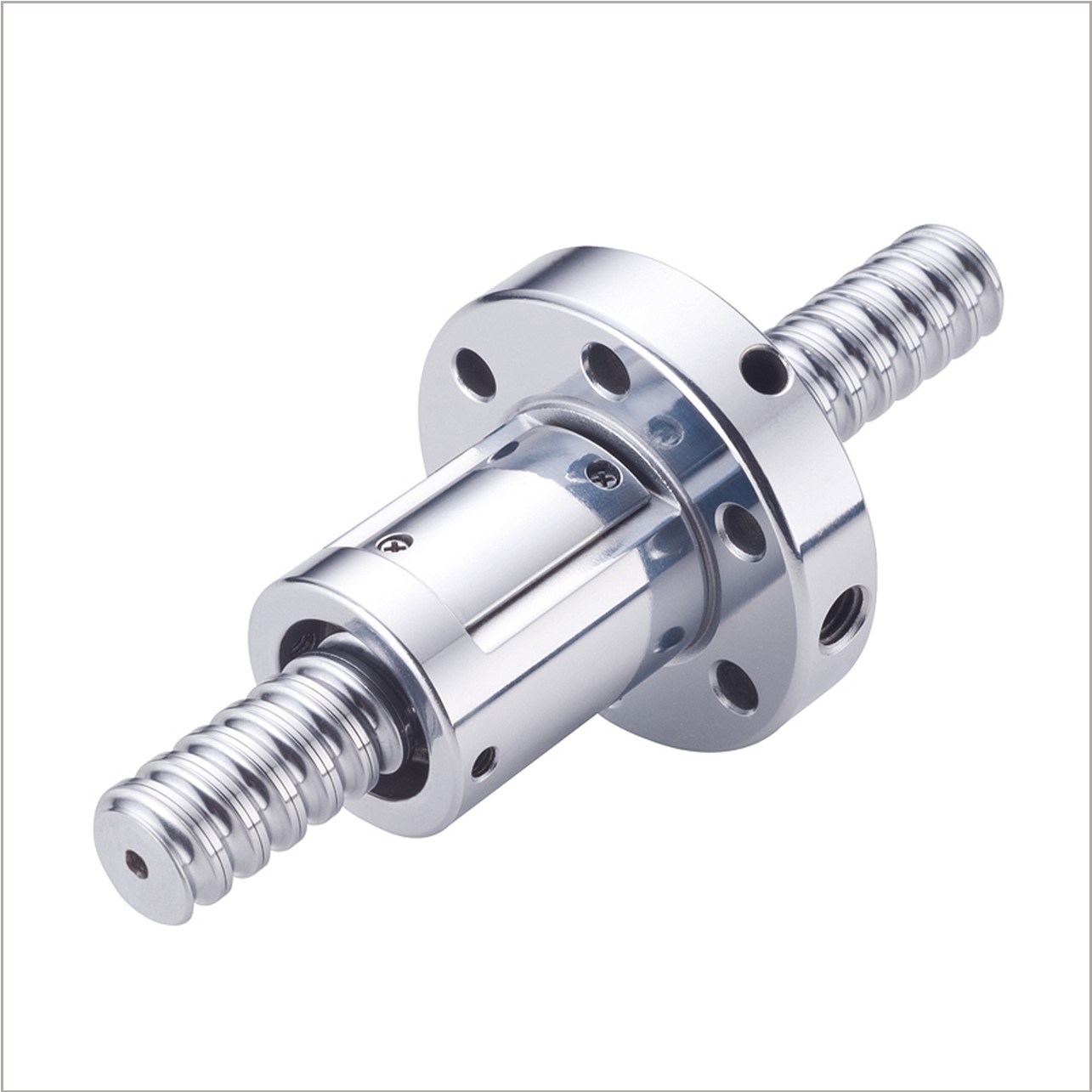
HIWIN Super Z Ballscrew
Price: ContactHigh Speed
DN value could reach 160,000.
High acceleration and deceleration
MAX 1.5G
Less Vibration & Smooth Operation
ompared with traditional tube circulation, Noise is lower (by) 3~5dB.
Space-saving and light weight design
The nut diameter is 15%~30% smaller than traditional series. -
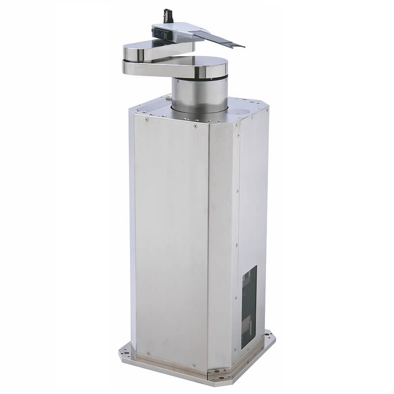
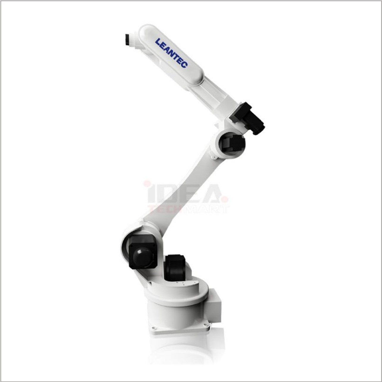
RWS Wafer Robot
Price: ContactFEATURES
- The advantage is on vertical integration of bothhardware and software, also using high precisionand stiffness DD motor, the repeatability can reach±0.1mm. Small circling radial and high utilizationof space.
- Applications include: Pick –and –place equipment inSemiconductor industry(pick-and place of wafer),Optoelectronics(mini panel, mini solar panel)andLED industry(sapphire substrate, rubber ring).
- Various options for end effectors such as vacuumtype, gripping type and flipping type. Able to providetotal solution to adapt to all kinds of customerapplications.
-
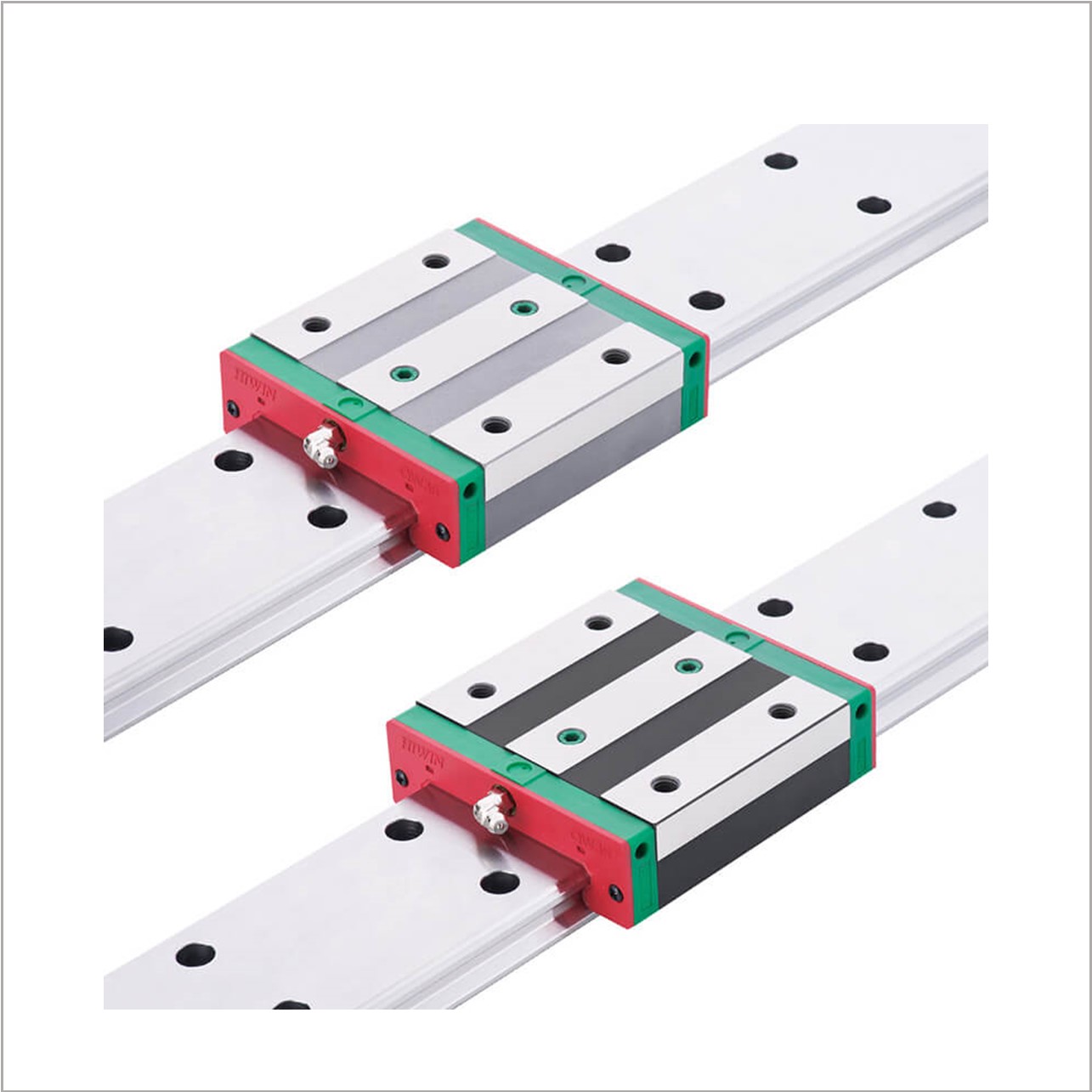
HIWIN QW Series Wide Rail Linear Guideway
Price: ContactFEATURE
The HIWIN QW series linear guideway with SynchMotionTM Technology possesses all the advantages of the WE series, which features high moment rigidity and is suitable for single rail or space saving applications. With the SynchMotionTM technology it also provides quieter and smoother movement, superior lubrication, and longer service life.
-
Miniature Circuit Breakers for Panelboard and Controlboard
Price: ContactNhiều chủng loại cầu dao cỡ nhỏ giúp mang lại khả năng lựa chọn đa dạng.
Các cầu dao này có nhiều loại kích thước khác nhau để sử dụng trong các bảng chuyển mạch hoặc bảng điện. Chúng có kích thước tương đối nhỏ.
-
Spindle Motors
Price: ContactNext-generation spindle motor, equipped with high speed and high efficiency.
High-performance New Type Spindle Motors SJ-D Series
Low-inertia, High-speed Spindle Motors SJ-DL Series
High-performance Spindle Motors SJ-V Series
Low-inertia,High-speed Spindle Motors SJ-VL Series
Tools Spindle Motors HF-KP/HF-SP Series
Built-in Spindle Motor SJ-BG Series
IPM Spindle Motor