How to read Japanese mechanical drawings (JIS)
Not everyone can understand deeply and read Japanese mechanical drawings properly. So how to read the drawing properly? Let’s learn with me how to read Japanese mechanical drawings in the article below.
What is the JIS standard?
JIS Standard (English: Japanese Industrial Standards) is a Japanese industrial standard used in industrial activities in this country.
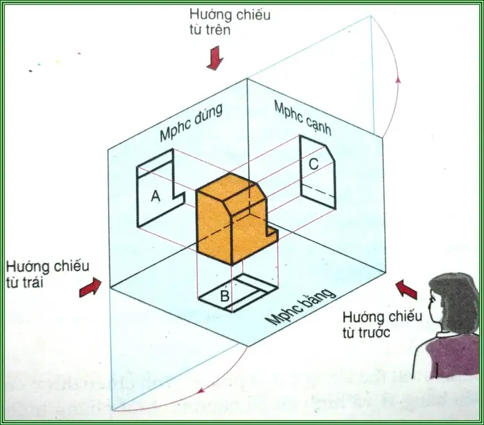
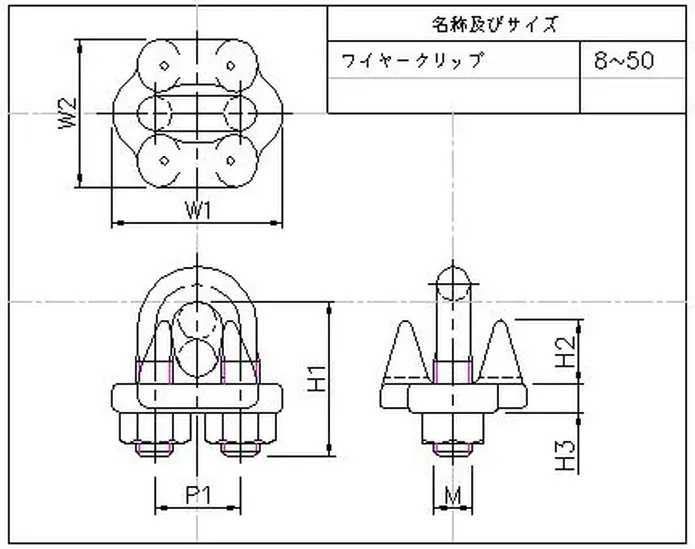
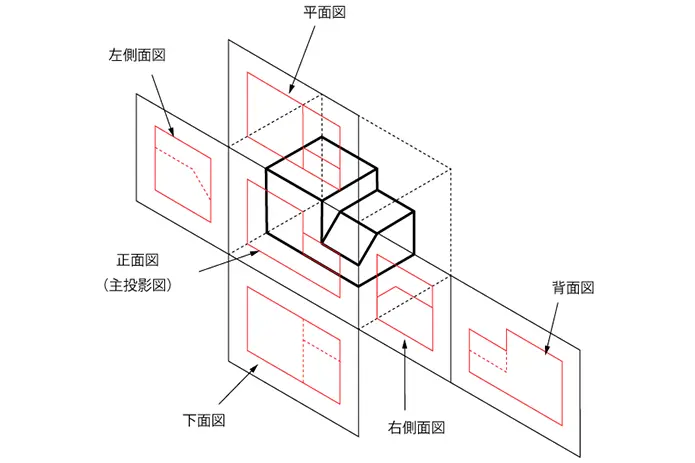
Unlike drawings in Vietnam, Japanese drawings have an edge-to-vertical projection layout and are used according to JIS standards – the 3rd angle projection method (illustration). In addition, when the processing details are complicated to clearly show the requirements to be processed, people will use cutting drawings and extract drawings.
Instructions on how to read Japanese mechanical drawings (JIS)
To understand how to layout and build projections according to JIS standards, please follow the reading below.
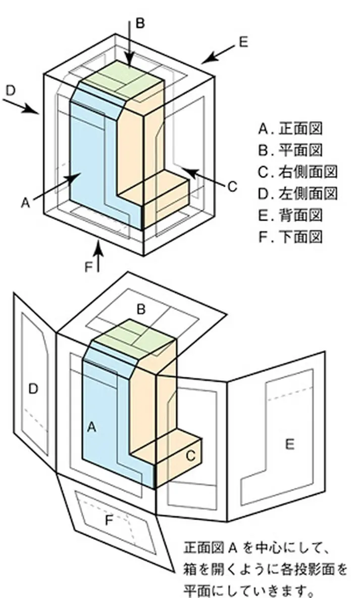
Suppose when there is a rectangular box with the symbol planes in the figure:
- Looking from the outside, you will see the object passing through the planes and showing the faces of the rectangular box with the corresponding lines (visible or hidden).
- If you open the planes of the box (shown below) you will get the corresponding projections of the object on the respective faces.
- The planes of the box that are spread on the same plane will be the projection planes of the object.
As a result, each object will have 6 corresponding planes, but usually only 3 faces are enough. If it’s simple, it’s 2 projections, while it’s complicated, it takes up to 6 faces to be projected and the cut and extracted images to show all the objects. In which, the projection always has the main view to be able to see the whole object.
Draw projection from bright object 2D model
In addition to applying the above standard, you also have to know how to imagine the object to be able to draw accurately and quickly.
– From the object, you will draw the following 2D projections:

– You will draw and arrange the corresponding projections as above.
When drawing, you must draw the faces that show the most clearly and easily visualize the object. At the same time, limit the dashed directions and the number of projections just enough to visualize the object.
From the projection of 2D models to build real objects
In order to build a real body from a 2D view, technicians need to master the rules of viewing the image above.
From 2D drawings to build objects, you must visualize 3D objects. This is the ultimate goal of reading engineering drawings.
– From the 2D projection, build the object as follows:
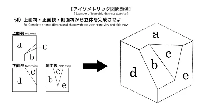
When starting to edit, you should sketch the object from the projection so that the image uses the object. Then, based on the remaining shapes to build the next object, you can cut or add blocks.
Reference source: blog.mecsu.vn
-
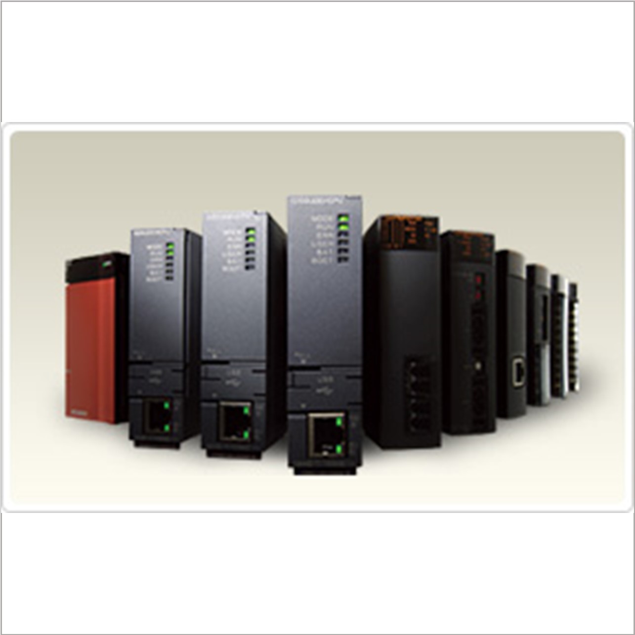
MELSEC-Q Series
Price: Contactナノオーダの高速な基本命令処理により装置、機械のパフォーマンスを飛躍的に向上するシーケンサ「MELSEC-Q」
日々高度化する生産設備や製造設備に対応して高速・高精度・大容量のデータ処理、マシン制御を実現します。
-
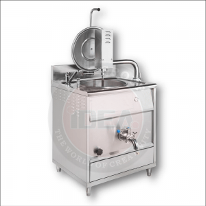
ボイラーと混合システム
Price: Contact仕様:
電圧::220V / 50HZ / 3 pha
容量: 68L
暖房能力: 12000W
サイズ: 770 (W) x960 (D) x1140/1800 (H) mm
重さ: 95kgs
-
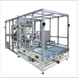
構造機械フレーム、溶接ビーム 11
Price: ContactITMCと合併会社は経験が豊富な溶接チームを持ち、ペッドフライス盤、大型の横型フライス盤を備え、最大の5.2x2.5大型ビームフレームを処理することができます。また、現地で投資した塗装設備により、スプーレ塗装と粉体塗装することが可能です。
あらゆるの分野での精密機械製品の供給を専門とするベトナムのトップ会社であることを誇りに思います。150社以上のパートナとの仕事経験を持ち、主に99%は日本や米国などのような最も厳しい市場から来ており、お客様に提供する製品は常に完璧と求められています。
各加工段階は切断、溶接、フライス加工、CNC加工、研磨、表面仕上げなどがあります。
ITMC加工製品は種類が豊富と多様で、最も厳しいお客様の要求でも対応できます。
-
5 サーボプレスJPFシリーズ5両手押しスイッチ仕様
Price: Contact-
主な特長
「労働安全衛生規則」準拠
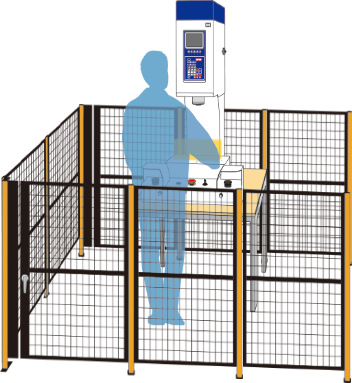
プレス用両手操作式安全装置を開発し、型式検定取得。ライトカーテン、エリアセンサなどの安全装置は不要です。コストを削減できるうえに、作業員の安全と広範囲の作業スペースが確保できます。
製造品質の向上
荷重表示の精度:±0.8%(FS) *最大荷重の5%以上の範囲での値
位置繰り返し精度:±0.005mm *本体温度が一定の場合トレーサビリティ(IoT)
高速サンプリングしたデータを全面ディスプレイに表示できます。USBメモリやイーサネット経由でPC等の外部機器に転送でき、品質管理に役立ちます。
・位置・荷重サンプリング間隔:0.25msec電動サーボモータにより省エネルギー
油圧・空圧プレスに比べ1/4~1/5のエネルギー*。トレーサビリティを要求される油圧・空圧プレスの置き換えに最適。
*当社調べセル生産に最適なオールインワン
結果表示・制御部・駆動部・C型フレーム・両手操作部が一体となり電源ONしてすぐに使用できます。
セル生産や研究開発にも最適です。多彩な加圧機能と豊富な判定機能
駆動条件(速度・荷重)と停止条件(位置・荷重・距離・時間など)を組み合わせた駆動モードを用意しています。豊富な判定機能により不良品の流出を防ぎます。
前面LCD表示のグローバル対応
13言語*対応で、海外の現地スタッフも対応できます。
*日本語、英語、中国語(簡体字・繁体字)、韓国語、ベトナム語、ドイツ語、フランス語、スペイン語、イタリア語、ルーマニア語、チェコ語、ハンガリー語。メンテナンス機能の充実
簡単設定でアンプ調整・荷重校正を行えます。油圧・空圧プレスに比べ、メンテナンスが容易でコストも削減可能。
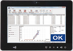
10.1インチユニット TaSIIS タッチパネルモニタ(Windowsベース)
プレス工程のパラメーターと結果グラフの閲覧・解析が可能。包括的なプレス工程管理がこの1台で行えます。
-